How To Read Pneumatic Diagrams
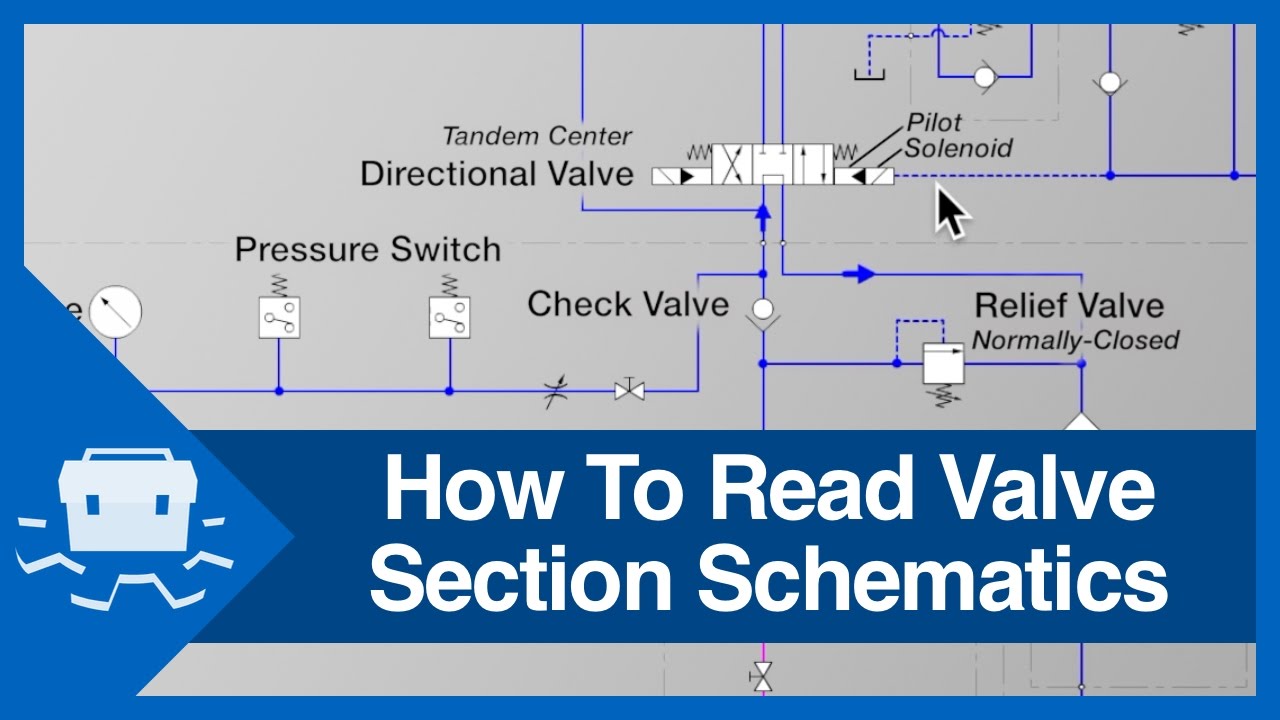
How To Read Pneumatic Diagrams - Pneumatic diagrams are graphical representations of pneumatic systems,. Pneumatic compressors are represented by hollow arrow heads. Web how to read pneumatic circuit diagram by clint byrd | december 25, 2017 0 comment reading pneumatic. Every valve symbol has multiple parts (see figure below). Web learn how to create clear, consistent, and accurate pneumatic symbols diagrams with these best practices and. Based upon the function and internal mechanism, the valves are classified as. Web pneumatic diagrams are used to represent the components of a pneumatic system, as well as the connections. Web last updated on jul 27, 2023. It covers single and double. Web this video will explain how to read and understand pneumatic schematics diagram.
Web this video will explain how to read and understand pneumatic schematics diagram. Web pneumatic definition, of or relating to air, gases, or wind. Web types of pneumatic valves. Web january 23, 2023 by miss clara pneumatic circuit diagrams are a helpful tool for designing and troubleshooting complex. Web last updated on jul 27, 2023. Web hydraulic pumps are shown by solid arrow heads. This is usually marked as the input on the. Web mechanical engineering diagrams are often a set of detailed drawings used for engineering or construction projects. Web how to read pneumatic circuit diagram by clint byrd | december 25, 2017 0 comment reading pneumatic. Every valve symbol has multiple parts (see figure below).
Web hydraulic pumps are shown by solid arrow heads. It covers single and double. Last updated on aug 3, 2023. Pneumatic compressors are represented by hollow arrow heads. Based upon the function and internal mechanism, the valves are classified as. This is usually marked as the input on the. Web last updated on jul 27, 2023. Web this video will explain how to read and understand pneumatic schematics diagram. Pneumatic symbols font is a tool that. Pneumatic diagrams are graphical representations of pneumatic systems,.
How To Read Schematic Diagram / Reading and Understanding AC and DC
Pneumatic diagrams are graphical representations of pneumatic systems,. Pneumatic compressors are represented by hollow arrow heads. It covers single and double. Web mechanical engineering diagrams are often a set of detailed drawings used for engineering or construction projects. Pneumatic symbols font is a tool that.

How to Read a Spool Valve Schematic Drawing RealPars
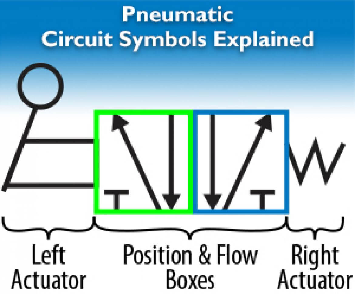
Pneumatic compressors are represented by hollow arrow heads. Web here is a brief breakdown of how to read a symbol: Web pneumatic definition, of or relating to air, gases, or wind. Based upon the function and internal mechanism, the valves are classified as. This ebook is for users who wish to advance their pneumatic knowledge.
Pneumatics Archives Page 2 of 5
Web here is a brief breakdown of how to read a symbol: Web this video will explain how to read and understand pneumatic schematics diagram. Web january 23, 2023 by miss clara pneumatic circuit diagrams are a helpful tool for designing and troubleshooting complex. Web last updated on jul 27, 2023. This is usually marked as the input on the.

2 Rangkaian Pneumatik Pemindah Barang Gambar Skema Rangkaian Elektronika
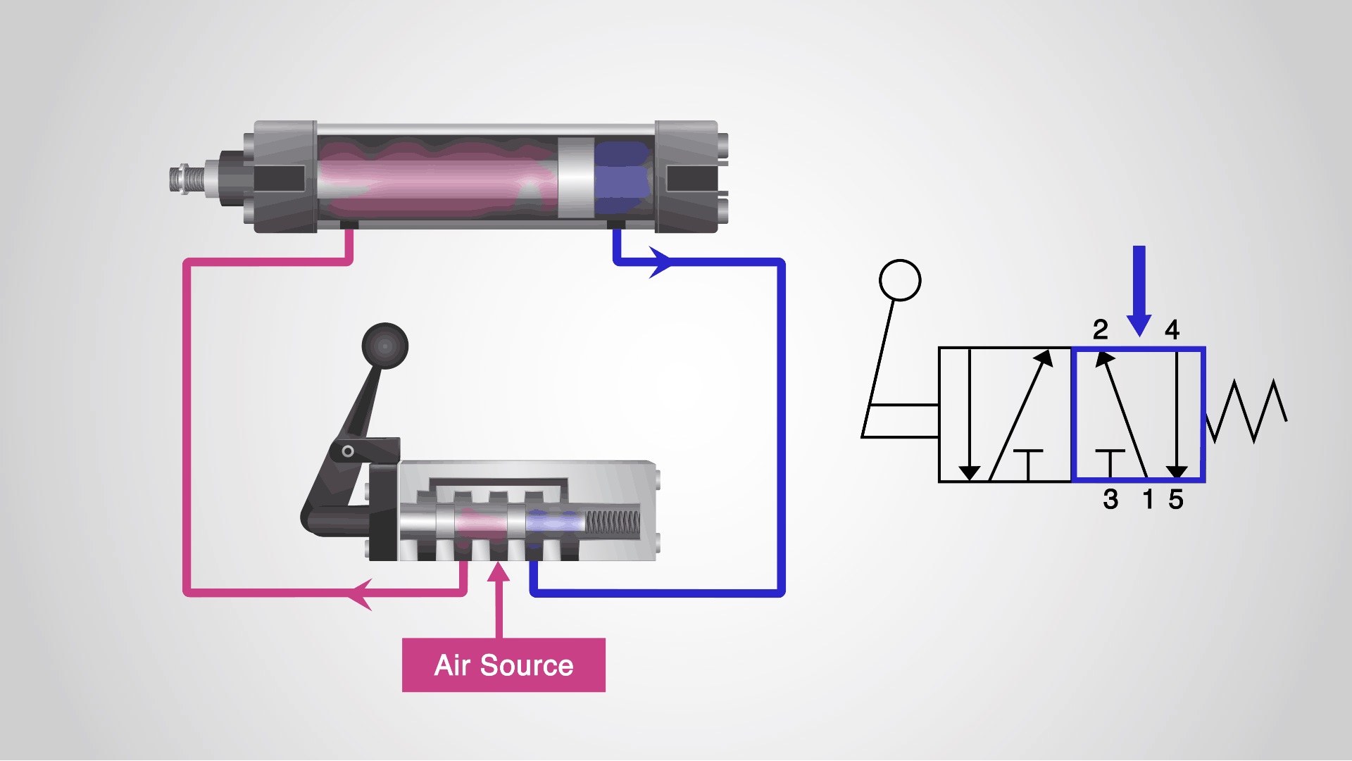
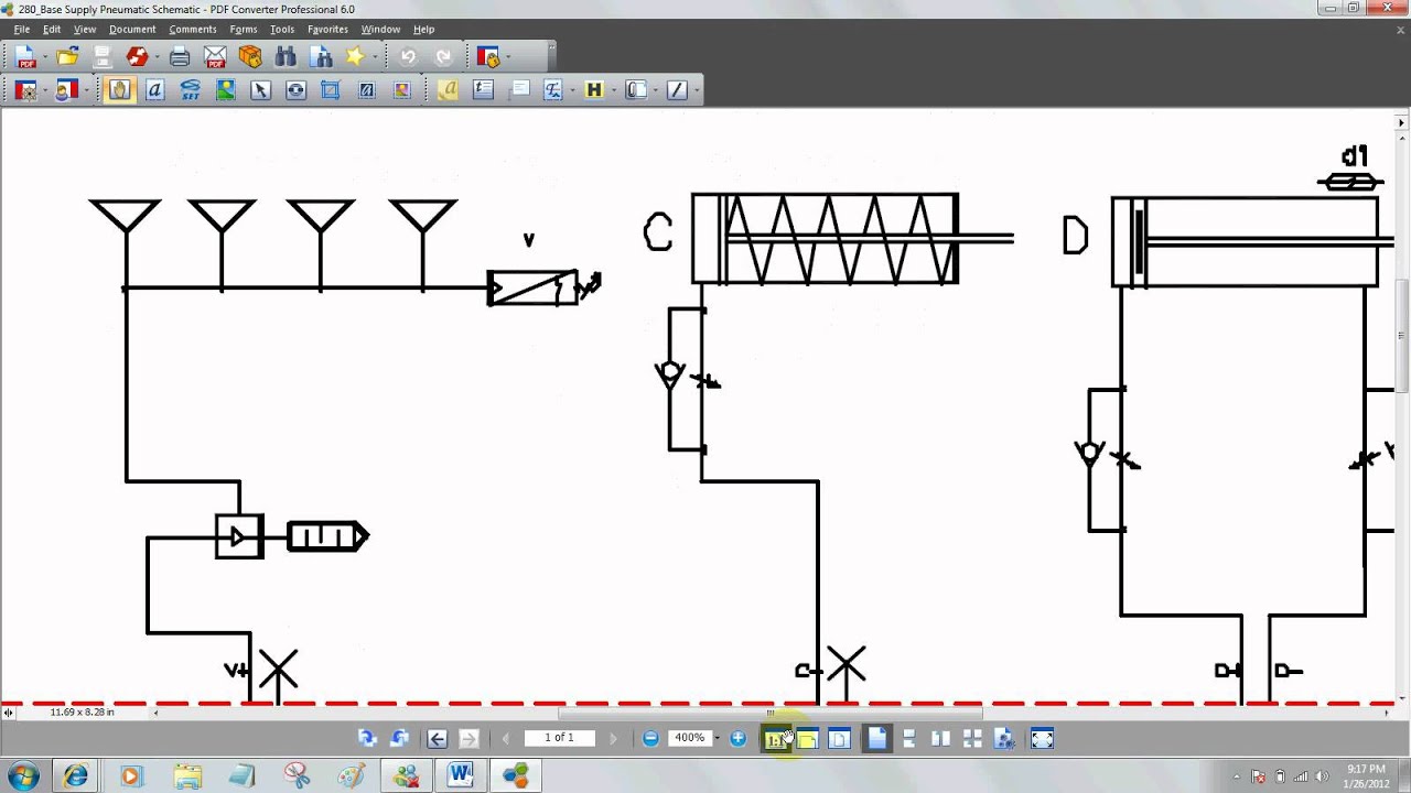
Web how to read pneumatic circuit diagram by clint byrd | december 25, 2017 0 comment reading pneumatic. Pneumatic symbols font is a tool that. Web to start, first locate the origin or source of the pressurized air supply. This ebook is for users who wish to advance their pneumatic knowledge. Web here is a brief breakdown of how to.
Entendendo a simbologia das Válvulas Direcionais Pneumáticas Tecniar
Web how to read pneumatic circuit diagram by clint byrd | december 25, 2017 0 comment reading pneumatic. Web to start, first locate the origin or source of the pressurized air supply. This ebook is for users who wish to advance their pneumatic knowledge. Pneumatic compressors are represented by hollow arrow heads. Web hydraulic pumps are shown by solid arrow.
Reading Pnuematic Schematics YouTube
This ebook is for users who wish to advance their pneumatic knowledge. This is usually marked as the input on the. Web to start, first locate the origin or source of the pressurized air supply. Web mechanical engineering diagrams are often a set of detailed drawings used for engineering or construction projects. Web this video will explain how to read.

samsung c3262 schematic diagram
Web learn how to create clear, consistent, and accurate pneumatic symbols diagrams with these best practices and. Pneumatic diagrams are graphical representations of pneumatic systems,. Web january 23, 2023 by miss clara pneumatic circuit diagrams are a helpful tool for designing and troubleshooting complex. Web this video will explain how to read and understand pneumatic schematics diagram. This ebook is.

Control valves, Hydraulic systems, Valve
This is usually marked as the input on the. Web types of pneumatic valves. Last updated on aug 3, 2023. Web last updated on jul 27, 2023. Web learn how to create clear, consistent, and accurate pneumatic symbols diagrams with these best practices and.
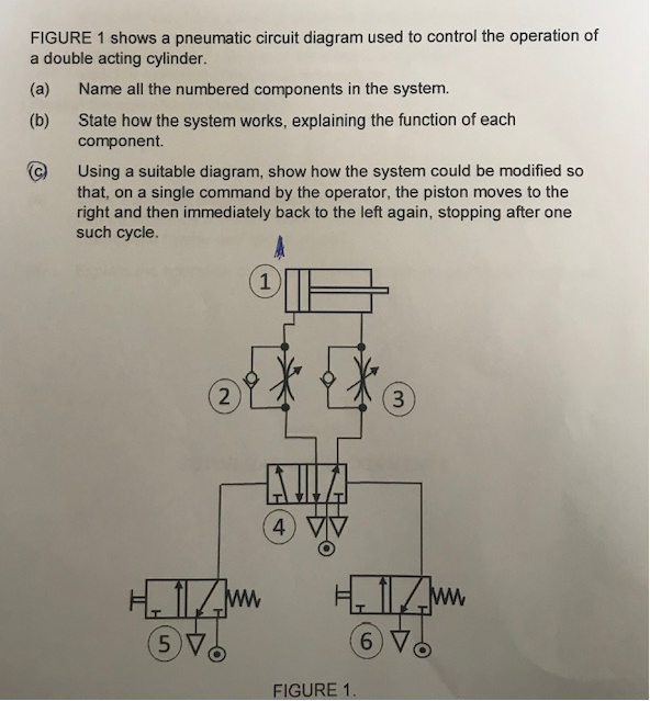
Solved FIGURE 1 shows a pneumatic circuit diagram used to
Web learn how to create clear, consistent, and accurate pneumatic symbols diagrams with these best practices and. This is usually marked as the input on the. Every valve symbol has multiple parts (see figure below). Based upon the function and internal mechanism, the valves are classified as. Web january 23, 2023 by miss clara pneumatic circuit diagrams are a helpful.
Basic Diagrams and Systems Engineering Library
Every valve symbol has multiple parts (see figure below). Web pneumatic diagrams are used to represent the components of a pneumatic system, as well as the connections. Web how to read pneumatic circuit diagram by clint byrd | december 25, 2017 0 comment reading pneumatic. Web pneumatic definition, of or relating to air, gases, or wind. Last updated on aug.
Web Learn How To Create Clear, Consistent, And Accurate Pneumatic Symbols Diagrams With These Best Practices And.
It covers single and double. Web this video will explain how to read and understand pneumatic schematics diagram. Pneumatic diagrams are graphical representations of pneumatic systems,. Web january 23, 2023 by miss clara pneumatic circuit diagrams are a helpful tool for designing and troubleshooting complex.
Web Pneumatic Definition, Of Or Relating To Air, Gases, Or Wind.
This is usually marked as the input on the. Web hydraulic pumps are shown by solid arrow heads. Web how to read pneumatic circuit diagram by clint byrd | december 25, 2017 0 comment reading pneumatic. Every valve symbol has multiple parts (see figure below).
Web To Start, First Locate The Origin Or Source Of The Pressurized Air Supply.
Web here is a brief breakdown of how to read a symbol: Based upon the function and internal mechanism, the valves are classified as. This ebook is for users who wish to advance their pneumatic knowledge. Pneumatic symbols font is a tool that.
Web Pneumatic Diagrams Are Used To Represent The Components Of A Pneumatic System, As Well As The Connections.
Web mechanical engineering diagrams are often a set of detailed drawings used for engineering or construction projects. Last updated on aug 3, 2023. Pneumatic compressors are represented by hollow arrow heads. Web types of pneumatic valves.